
Before using a code: this is a learning reference, not a machine-ready program. Verify the exact controller manual, setup, tools and offsets; simulate and complete a supervised prove-out.
Choose a cycle. Follow every move.
Each lesson includes an original toolpath diagram, the movement sequence, parameter meanings, a worked learning example and checks that matter at the machine. The examples below use Haas control conventions unless a different version is explicitly named. This is not a universal FANUC or Siemens syntax list.
No matching lesson. Try a code such as G71 or clear the search.
LESSON 01 / TURNING
G70 · Profile finishing after roughing
Haas lathe · controller-specific learning example
G70 follows an already defined finished contour. Use it after suitable G71, G72 or G73 roughing has left a controlled finishing allowance. It does not calculate a new shape or choose an allowance for you. A separate finishing tool can improve access and surface finish.
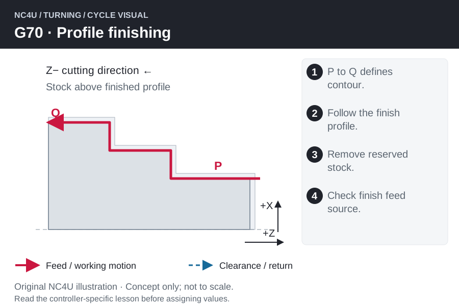
How the cycle works
- Position the selected finishing tool at a clear start point; verify its offset and nose geometry.
- Call the P-to-Q block range that describes the finished profile.
- Follow the contour using the effective feed, speed and tool commands in that range.
- After Q, return rapidly to the saved start position, then continue after the G70 call.
Read the program words
| Word | Meaning |
|---|---|
P | First contour block number, not a physical coordinate. |
Q | Last contour block number; it is included in the finishing path. |
F / S / T | Commands inside the contour range take effect during finishing. |
Read the cycle format
A syntax sketch with placeholders, not a complete runnable program.
G70 P[first-block] Q[last-block]Worked learning example
Suppose roughing leaves an outside diameter of 40.4 mm for a required 40.0 mm. The finishing tool removes 0.2 mm radially. Inspect the remaining stock before assuming the finish insert can handle every shoulder in one pass.
Common mistakes and setup checks
- Keep the return path clear of shoulders, jaws and the remaining stock.
- Check the finished size and surface requirement against the drawing; G70 is not an inspection result.
G71 removes the bulk of the stock in longitudinal passes; G70 follows the final contour. Haas permits some contour subprogram arrangements that are not FANUC-compatible.
LESSON 02 / TURNING
G71 · Longitudinal stock removal
Haas lathe · controller-specific learning example
G71 roughs an outside or inside profile with repeated cuts generally parallel to Z. Define the final contour once; the control calculates roughing passes around it while retaining specified stock for finishing. The drawing shows an OD example, not the mirrored path for every tool orientation.
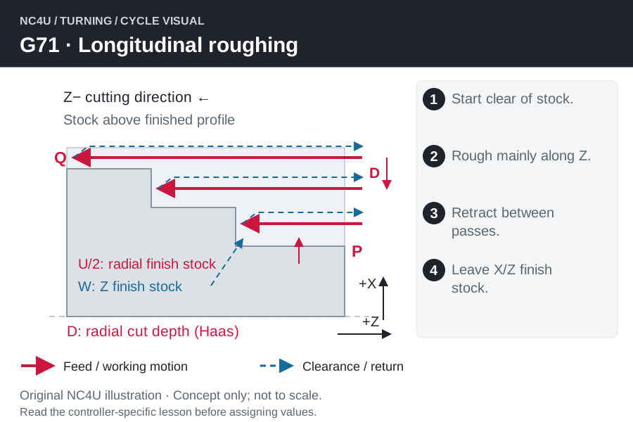
How the cycle works
- Establish a clear start outside the stock and define the P–Q profile in the XZ plane.
- Step inward for the next depth, then cut longitudinally toward the contour boundary.
- Retract clear and return toward the starting Z clearance before the next pass.
- Complete roughing with the specified allowances; use a suitable finishing operation afterward.
Read the program words
| Word | Meaning |
|---|---|
P / Q | First and last blocks of the final contour. |
D | One-block format: roughing depth measured radially. |
U / W | Finish stock: U is diametral X allowance; W is axial Z allowance. |
I / K | Optional extra rough-pass allowances: I radial, K axial. |
F | Roughing feed, interpreted with lathe G98 or G99. |
Read the cycle format
A syntax sketch with placeholders, not a complete runnable program.
G71 P[first] Q[last] D[radial-cut] U[diameter-stock] W[Z-stock] F[feed]Worked learning example
Diameter arithmetic: reducing a 50 mm blank to 46 mm removes 2 mm radially. A 1 mm radial step changes the diameter by 2 mm. Separately, U0.4 in the finish-allowance position leaves 0.2 mm on each radial side; it does not request a 0.4 mm cut.
Read the alternative format carefully
Reading the two-block form documented in the Haas NGC 2017 manual: the first G71 line uses U for radial depth per pass and R for retract amount. The second G71 line uses U for diametral finishing allowance, alongside P/Q contour blocks, W axial allowance and F feed. Thus U1.0 on the first line and U0.2 on the second do different jobs: a 1.0 mm radial roughing step versus 0.1 mm radial finish stock. R1.0 is a retract amount, not a work-coordinate R plane. This explains the supplied two-line example; it is not a universal FANUC program.
G71 U[radial-cut] R[retract]
G71 P[first] Q[last] U[diameter-stock] W[Z-stock] F[feed]
Common mistakes and setup checks
- Haas Type I does not allow X reversal in the contour; Type II allows it, but Z must not reverse in either type.
- Do not mix a two-block U/R setup with the one-block D interpretation. Starting position, allowance signs and tool access still determine clearance.
G72 primarily cuts across the face. G73 follows repeated offset contours. G71 is appropriate when longitudinal roughing fits the blank and profile.
LESSON 03 / TURNING
G72 · Face stock removal
Haas lathe · controller-specific learning example
G72 roughs a face-oriented profile by repeated cuts mainly along X. It is useful when the material should be removed across the face rather than lengthwise along a shaft. The final shape still comes from a P–Q contour, and finishing stock must be planned separately.
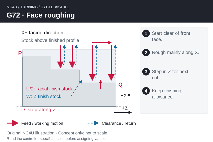
How the cycle works
- Start clear of the blank face and outside the cutting envelope.
- Advance to the next axial cutting level, then feed across the face along X.
- Retract and return to the clearance position before the next face pass.
- Follow the rough contour while preserving U/W finishing stock, then return to the saved start.
Read the program words
| Word | Meaning |
|---|---|
P / Q | Contour block boundaries. |
D | Cut depth for one-block G72; separation of successive face cuts. |
U / W | X finishing allowance is diametral; Z allowance is axial. |
F | Roughing feed selected with the active lathe feed mode. |
Read the cycle format
A syntax sketch with placeholders, not a complete runnable program.
G72 P[first] Q[last] D[cut-depth] U[diameter-stock] W[Z-stock] F[feed]Worked learning example
For a face with 3 mm of axial excess, think of layers across the face. If the planned roughing step is 1 mm, each layer is 1 mm farther in Z. The final layer must preserve the chosen finishing stock, rather than automatically reaching the drawing face.
Common mistakes and setup checks
- A facing insert needs clearance and cutting ability across the full X travel, including any approach toward centre.
- Check Type I/II profile restrictions and the control-specific P-block rule; do not infer them from G71 alone.
G71 repeats Z-directed roughing cuts; G72 repeats X-directed face cuts. G94 is a simpler facing loop where the programmer supplies subsequent depths.
LESSON 04 / TURNING
G73 · Contour-repeat roughing
Haas lathe · controller-specific learning example
On a lathe, G73 removes material by repeating shifted versions of the finished profile. This can suit a casting or forging that already resembles the component. It assumes a known stock envelope; it does not discover empty space or automatically avoid all unmodelled stock.
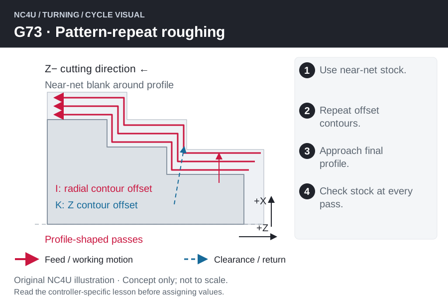
How the cycle works
- Define the final P–Q profile and measure the preform stock offsets.
- Approach the first shifted contour using the movement defined at P.
- Cut that contour, depart clear and repeat closer to the final shape.
- After the planned pass count, leave U/W finish stock and return to the start.
Read the program words
| Word | Meaning |
|---|---|
D | Positive integer number of contour passes, not depth of cut. |
I / K | Total shift from first to last rough contour: I radial X, K axial Z. |
U / W | Final roughing leaves U/2 radially and W axially. |
P / Q | Start and end of the contour to repeat. |
Read the cycle format
A syntax sketch with placeholders, not a complete runnable program.
G73 P[first] Q[last] I[radial-shift] K[Z-shift] D[pass-count] U[diameter-stock] W[Z-stock] F[feed]Worked learning example
With I = 3 mm and D = 4 passes, the radial shift between successive contours is 3 ÷ (4 − 1) = 1 mm. U0.4 leaves a separate 0.2 mm radial finishing allowance. This is geometric arithmetic, not a recommended cut for a particular casting.
Common mistakes and setup checks
- Inspect approach and departure through the actual casting envelope, including interrupted surfaces.
- Do not confuse lathe G73 with the milling chip-break drilling cycle.
A solid cylindrical blank often calls for a different roughing strategy. Choose G73 because the preform fits offset contours, not merely because the final drawing is curved.
LESSON 05 / TURNING
G74 · End-face peck grooving
Haas lathe · controller-specific learning example
G74 advances mainly along Z into the end face. With a face-grooving tool it can create an annular groove; with a suitable axial drilling setup it also supports peck drilling. Groove width and tool access are physical limits that the cycle cannot infer.
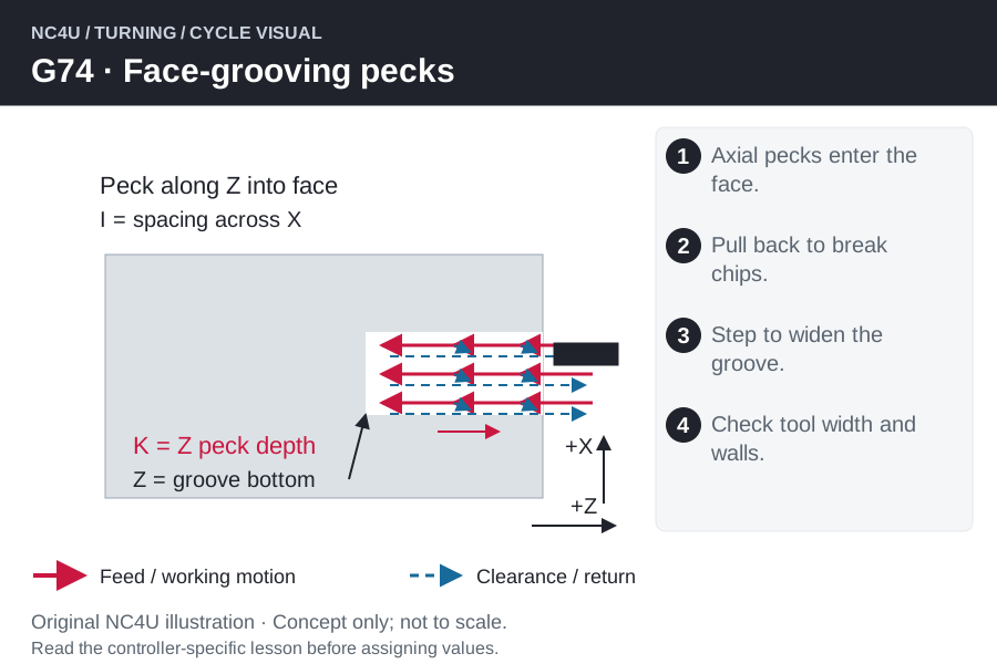
How the cycle works
- Position at the first radial location with the tool clear of the face.
- Feed into the face by a K-sized peck, then make the configured chip-relief retract.
- Repeat toward final Z depth and return clear.
- If additional X positions are specified, step across by I and repeat the peck sequence.
Read the program words
| Word | Meaning |
|---|---|
Z / W | Final axial depth: absolute Z or incremental W. |
K | Axial depth increment for each peck. |
X / I | X is final diametral location; I is diametral spacing between peck positions. |
D | Optional radial clearance shift; may collide with a closed groove wall. |
Read the cycle format
A syntax sketch with placeholders, not a complete runnable program.
G74 Z[depth] K[axial-peck] F[feed]Worked learning example
For a 6 mm-deep face groove, sketch three nominal 2 mm axial advances before choosing actual cutting data. If I changes diameter by 2 mm, adjacent groove positions are only 1 mm apart radially. Compare that spacing with the insert width to understand overlap.
Common mistakes and setup checks
- A face-grooving holder must fit the permitted groove diameter range.
- Do not add D inside a groove bounded on both sides; the lateral shift can break the tool.
- Version check: the current Haas web reference defines I as diametral spacing; some older manuals describe it differently. Confirm the manual matching the machine software before entering I.
G75 pecks radially into OD/ID grooves. G74 pecks axially into the face; its I and K meanings therefore differ from G75.
LESSON 06 / TURNING
G75 · Radial OD/ID peck grooving
Haas lathe · controller-specific learning example
G75 feeds into a groove along X, with relief between pecks to help break chips. It can repeat at additional Z positions. It is useful for radial grooves, but a wide groove still needs a strategy compatible with the insert width, side-cutting capability and chip space.
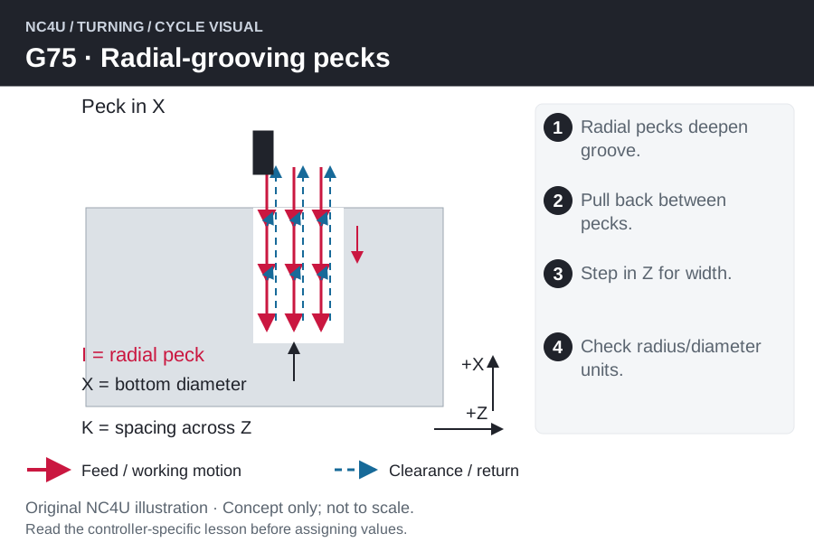
How the cycle works
- Set the tool at the groove Z location and at a clear starting diameter.
- Peck radially toward the target X, relieving between cuts.
- Return clear of the groove once the radial depth is reached.
- When Z/K is used, move to the next axial station and repeat.
Read the program words
| Word | Meaning |
|---|---|
X / U | Final groove-bottom diameter, or incremental diametral change. |
I | Radial peck depth; not a diametral peck value. |
Z / K | Last axial position and spacing between groove stations. |
F | Cutting feed; confirm the selected lathe feed mode. |
Read the cycle format
A syntax sketch with placeholders, not a complete runnable program.
G75 X[bottom-diameter] I[radial-peck] F[feed]Worked learning example
An OD groove from diameter 40 to diameter 34 is 3 mm deep radially. At a hypothetical I = 1 mm, the geometry contains three radial increments, not six. If the insert is 2 mm wide, the groove-edge dimensions must also account for which tool edge defines its Z offset.
Common mistakes and setup checks
- Check minimum internal clearance for ID work and the relief distance configured by the control.
- A Z step larger than the cutting width can leave ribs; a too-small step may increase rubbing.
The grooving depth I is radial even though the endpoint X is diametral. This is one of the most important distinctions to read before a G75 prove-out.
LESSON 07 / TURNING
G76 · Multiple-pass thread cutting
Haas lathe · controller-specific learning example
G76 deepens a thread through several synchronised passes. The thread specification defines the lead and geometry; the cycle distributes the cuts according to the Haas arguments and settings. It can cut straight or tapered threads. A valid cycle call does not establish the correct thread fit or inspection method.

How the cycle works
- Prepare the blank or bore, relief and clear start ahead of the thread.
- Synchronise the cutting move with spindle rotation at the specified lead.
- Pull out and return for a deeper pass using the selected infeed strategy.
- Complete the final passes and verify the thread with the required gauge or measurement.
Read the program words
| Word | Meaning |
|---|---|
X / Z | Target thread depth diameter and axial end position. |
K | Thread height measured radially, not diameter reduction. |
D | Depth of the first cut. |
F | Thread lead: axial travel per revolution. |
I / A | I is radial taper amount; A specifies the tool nose angle. |
Read the cycle format
A syntax sketch with placeholders, not a complete runnable program.
G76 X[depth-diameter] Z[end] K[radial-height] D[first-cut] F[lead]Worked learning example
For a two-start thread with 1.5 mm pitch, lead is 3.0 mm/rev. A single-start thread at the same pitch has 1.5 mm/rev lead. Neither figure specifies K: thread form, tolerance and crest/root truncation must still determine the required depth.
Common mistakes and setup checks
- Check run-out space, finish allowance and chamfer settings before the last shoulder.
- Do not paste packed-P two-block FANUC parameters into this Haas one-block format.
G92 needs programmer-chosen pass diameters. G32 gives a synchronised cutting move without an automatic return. G76 automates the multiple-pass strategy.
LESSON 08 / TURNING
G90 · Simple longitudinal turning loop
Haas lathe · controller-specific learning example
On a Haas lathe, G90 is a turning cycle, not the mill absolute-position command. It creates a repeatable straight or tapered cut and a return loop. The programmer chooses each additional pass diameter, so the cycle is useful for a simple cylindrical region without a long P–Q profile.
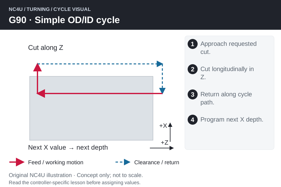
How the cycle works
- Start outside the stock with Z clear of the end face.
- Move to the commanded cutting diameter and feed to the Z endpoint.
- Withdraw and return along the cycle loop to the starting region.
- Enter another X pass diameter while G90 remains active, or select another motion mode to finish.
Read the program words
| Word | Meaning |
|---|---|
X / Z | Absolute cut endpoint; X is diametral in the illustrated mode. |
U / W | Incremental alternatives for X/Z. |
I | Optional signed radial taper amount. |
F | Feed in the active lathe feed mode. |
Read the cycle format
A syntax sketch with placeholders, not a complete runnable program.
G90 X[diameter] Z[end] F[feed]Worked learning example
A learning sketch might show successive diameters of 48, 46 and 44 mm on a 50 mm blank. Each 2 mm diameter change is a 1 mm radial increment. A real plan must still set the finish diameter, allowances and tool-specific cutting load.
Common mistakes and setup checks
- The rapid side of the loop must clear the remaining stock and any shoulder.
- Do not leave the modal cycle active before an unrelated coordinate block.
G71 calculates roughing passes from a contour; G90 relies on the pass endpoints that you provide.
LESSON 09 / TURNING
G92 · Threading with explicit pass diameters
Haas lathe · controller-specific learning example
G92 cuts a thread and returns through a cycle loop. The programmer specifies successive diameters to deepen the thread. This gives direct control over the pass schedule, but also makes the programmer responsible for reasonable infeed, a consistent lead and sufficient end relief.
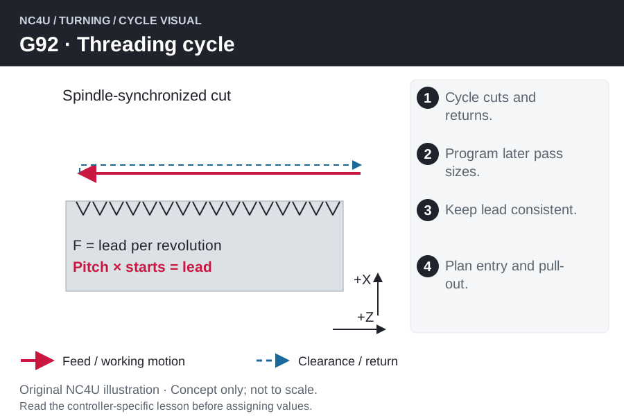
How the cycle works
- Prepare the thread blank or bore and establish a clear synchronisation approach.
- Execute one threading pass at the specified X, Z and lead.
- Allow the cycle to pull out and return to its starting position.
- Supply the next depth diameter; repeat until the planned thread geometry is achieved.
Read the program words
| Word | Meaning |
|---|---|
X / Z | Current pass depth diameter and thread endpoint. |
F | Lead, not an independently chosen cutting feed. |
I | Optional radial taper quantity. |
Q | Optional thread-start angle with Haas-specific input convention. |
Read the cycle format
A syntax sketch with placeholders, not a complete runnable program.
G92 X[pass-diameter] Z[end] F[lead]Worked learning example
If successive OD thread pass diameters differ by 0.20 mm, the added radial depth is 0.10 mm. Equal diameter changes do not necessarily create equal cutting loads because the engaged thread flank area grows as the groove deepens.
Common mistakes and setup checks
- Verify automatic thread chamfer settings and run-out space.
- Keep spindle synchronisation conditions consistent across passes and confirm the final thread using the drawing requirement.
Use G76 when its automatic infeed strategy suits the thread. G92 is not the mill coordinate-shift command, and its pass schedule is not calculated from K/D as in G76.
LESSON 10 / TURNING
G94 · Simple end-facing loop
Haas lathe · controller-specific learning example
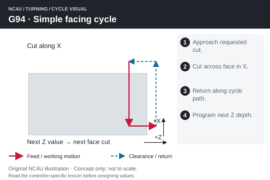
Haas lathe G94 performs a facing cycle. It is not the mill feed-per-minute command. The cut travels across the face and returns, while the programmer chooses further Z depths. A conical face can be specified with the relevant taper argument when the geometry and tool support it.
How the cycle works
- Position outside the stock diameter with sufficient front clearance.
- Approach the chosen Z cutting level.
- Feed across the face toward the X endpoint, then withdraw and return.
- Provide a new Z depth for another pass or change motion mode before leaving the operation.
Read the program words
| Word | Meaning |
|---|---|
X / Z | Face-cut endpoint and axial level. |
U / W | Incremental X/Z alternatives; U follows diameter convention. |
K | Optional Z-direction coning quantity. |
F | Feed interpreted with lathe G98/G99. |
Read the cycle format
A syntax sketch with placeholders, not a complete runnable program.
G94 X[face-end] Z[face-level] F[feed]Worked learning example
If the face must move from Z0 to Z−2 mm, a conceptual schedule at −0.8, −1.6 and a finishing level separates rough layers from the final dimension. The actual levels should be based on stock condition and the chosen finishing allowance.
Common mistakes and setup checks
- Consider tool clearance near centre, holder reach and maximum spindle speed if constant surface speed is used.
- Check the return leg; facing a recess may leave walls that obstruct a simple rectangular loop.
G72 uses a full profile and stock-removal strategy. G94 is the simpler cycle for explicit face levels; lathe feed per minute is G98.
LESSON 11 / TURNING
G32 · Synchronised thread-cutting motion
Haas lathe · controller-specific learning example
G32 is a synchronised motion command rather than a complete canned cycle. It connects axis travel to spindle rotation, allowing a programmed threading path. You must provide the entry, withdrawal, return and every additional pass; no automatic return is supplied at the end of the cut.

How the cycle works
- Establish the intended constant spindle speed and feed-per-revolution mode.
- Enter the threading move with a known start and the required lead.
- Continue the programmed threading path and explicitly define the exit.
- Cancel G32 with a different Group 01 motion before returning and repeating at the next depth.
Read the program words
| Word | Meaning |
|---|---|
X / Z | Axis endpoints of the threading motion; at least one axis move is required. |
F | Thread lead in the supported feed-per-revolution interpretation. |
Q | Optional start angle; Haas uses thousandths of a degree without a decimal point. |
Read the cycle format
A syntax sketch with placeholders, not a complete runnable program.
G32 Z[thread-end] F[lead]Worked learning example
For a straight single-start 2 mm-pitch thread, each spindle revolution corresponds to 2 mm axial travel. A 20 mm cutting length therefore spans ten revolutions geometrically; approach, acceleration and withdrawal add time beyond that simple calculation.
Common mistakes and setup checks
- On Haas, feed override is ignored and feed hold/single-block stopping is deferred through the G32 sequence.
- Do not change actual spindle RPM between repeated passes; never assume a reset or G80 substitutes for cancelling this Group 01 motion.
G92 adds a return loop; G76 also organises multiple passes. Choose G32 only when the explicitly programmed threading path is justified.
LESSON 12 / TURNING
G81 · Axial drilling in one feed stroke
Haas lathe · controller-specific learning example
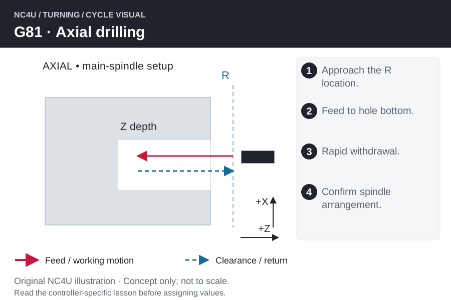
G81 drills along the axial hole direction with one continuous feed stroke and a rapid withdrawal. On a lathe, an on-centre stationary drill may cut while the work rotates; off-centre face drilling requires the appropriate live-tool and positioning setup. The cycle name alone does not select that hardware.
How the cycle works
- Identify an on-centre axial or supported live-tool setup, then position clear of the intended hole.
- Approach the R position with a verified tool/work offset.
- Feed continuously from R to the programmed bottom Z, without an intentional dwell or peck.
- Retract rapidly out of the hole to the cycle return clearance.
Read the program words
| Word | Meaning |
|---|---|
R | Axial approach-plane position, chosen from the actual face and clearance. |
Z | Axial bottom coordinate; distinguish tool-tip depth from full feature depth. |
F | Feed: identify the active lathe feed mode and the rotating spindle. |
Read the cycle format
A syntax sketch with placeholders, not a complete runnable program.
G81 Z[bottom] R[approach] F[feed]Worked learning example
For a faced part at Z0 and a planned drill-tip endpoint at Z−18 mm, an R position of Z+2 mm gives 20 mm of feed travel from R. The full-diameter hole depth is less than the drill-tip depth unless drill-point geometry is allowed for.
Common mistakes and setup checks
- A long hole or poor chip flow may need a different process; G81 supplies no chip-clearing pecks.
- Cancel the hole cycle with G80 before unrelated positioning. Lathe G98/G99 select feed units; they are not milling return-plane commands.
G82 adds a bottom dwell; G83 interrupts the feed with chip-clearing withdrawals. Choose by tool and chip behaviour rather than by code-number order.
LESSON 13 / TURNING
G82 · Axial spot drilling with dwell
Haas lathe · controller-specific learning example
G82 feeds to a specified axial depth, pauses there and withdraws rapidly. A spot or counterbore operation may use the pause to clean the bottom, but dwell is a process choice rather than a guarantee of better finish. Too much stationary contact can increase heat and rubbing.

How the cycle works
- Identify an on-centre axial or supported live-tool setup, then position clear of the intended hole.
- Approach the R position with a verified tool/work offset.
- Feed from R to the specified Z, then dwell at that depth for the programmed P duration.
- After the dwell, withdraw rapidly to the clear return position.
Read the program words
| Word | Meaning |
|---|---|
R | Axial approach-plane position, chosen from the actual face and clearance. |
Z | Axial bottom coordinate; distinguish tool-tip depth from full feature depth. |
F | Feed: identify the active lathe feed mode and the rotating spindle. |
P | Bottom dwell; confirm time units for this control. |
Read the cycle format
A syntax sketch with placeholders, not a complete runnable program.
G82 Z[bottom] R[approach] P[dwell] F[feed]Worked learning example
In ideal geometry, a 90-degree included-angle spot tool produces a 4 mm-diameter spot at 2 mm depth from its theoretical sharp tip. A real tool may have a flat or radius, so use its actual geometry when relating Z depth to spot diameter.
Common mistakes and setup checks
- Confirm P input units and decimal convention. Do not assume a copied P value means the same time on another control.
- Cancel the hole cycle with G80 before unrelated positioning. Lathe G98/G99 select feed units; they are not milling return-plane commands.
G81 has no deliberate bottom dwell. G89 also dwells, but its boring withdrawal is at feed rather than the G82 rapid return.
LESSON 14 / TURNING
G83 · Axial peck drilling with chip clearing
Haas lathe · controller-specific learning example
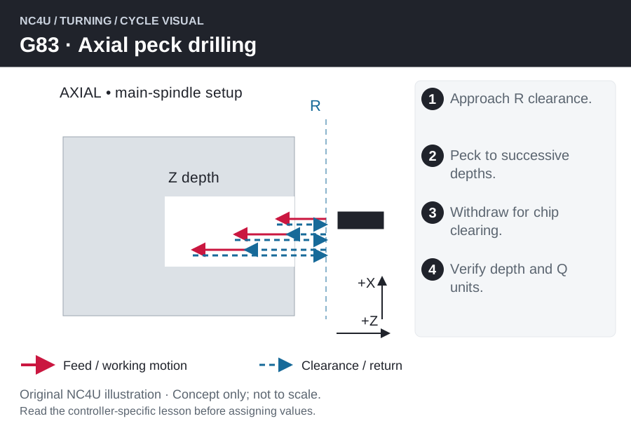
G83 breaks a deeper axial drilling operation into successive depths with withdrawal for chip clearing. It is useful when continuous drilling would trap chips. The process still needs appropriate drill geometry, coolant delivery and peck size; simply selecting G83 does not make every deep hole practical.
How the cycle works
- Identify an on-centre axial or supported live-tool setup, then position clear of the intended hole.
- Approach the R position with a verified tool/work offset.
- Feed to the next peck depth, withdraw for chip clearing, then re-approach near the previous depth before feeding deeper.
- Repeat until final Z is reached, then complete the cycle return; configured clearances affect the actual retract distances.
Read the program words
| Word | Meaning |
|---|---|
R | Axial approach-plane position, chosen from the actual face and clearance. |
Z | Axial bottom coordinate; distinguish tool-tip depth from full feature depth. |
F | Feed: identify the active lathe feed mode and the rotating spindle. |
Q | Constant peck increment, not the absolute bottom coordinate. |
I / J / K | Alternative variable-peck mode: first peck, reduction, minimum peck. |
Read the cycle format
A syntax sketch with placeholders, not a complete runnable program.
G83 Z[bottom] R[approach] Q[peck] F[feed]Worked learning example
For a conceptual feed interval of 22 mm and a constant Q increment of 5 mm, the depth increments are 5, 5, 5, 5 and 2 mm. These are increments along the cycle feed direction, not five identical 5 mm final-depth coordinates.
Common mistakes and setup checks
- Use either constant Q or the Haas I/J/K variable-peck method, not both. Setting 52 can extend the clear move beyond R.
- Cancel the hole cycle with G80 before unrelated positioning. Lathe G98/G99 select feed units; they are not milling return-plane commands.
For G83, chip clearing is part of the repeated sequence. Lathe G73 means contour-repeat roughing, so do not substitute the mill G73 drilling meaning here.
LESSON 15 / TURNING
G85 · Axial boring with feed withdrawal
Haas lathe · controller-specific learning example
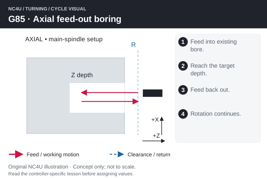
G85 feeds into an axial bore and feeds back out while rotation continues. It suits an operation where controlled withdrawal is preferable to a rapid exit. Boring normally enlarges an existing hole: the starting bore must already give the tool and shank enough space.
How the cycle works
- Identify an on-centre axial or supported live-tool setup, then position clear of the intended hole.
- Approach the R position with a verified tool/work offset.
- Advance at the selected feed from the approach plane to final Z.
- Reverse axial travel at feed with rotation still active, then regain clear space before positioning elsewhere.
Read the program words
| Word | Meaning |
|---|---|
R | Axial approach-plane position, chosen from the actual face and clearance. |
Z | Axial bottom coordinate; distinguish tool-tip depth from full feature depth. |
F | Feed: identify the active lathe feed mode and the rotating spindle. |
Read the cycle format
A syntax sketch with placeholders, not a complete runnable program.
G85 Z[bottom] R[approach] F[feed]Worked learning example
If the tool travels 15 mm inside a bore on entry and 15 mm on withdrawal, that portion totals 30 mm of feed movement. At a hypothetical 100 mm/min it takes 18 seconds, excluding approach and acceleration. Feed-out is not a rapid-time shortcut.
Common mistakes and setup checks
- Check whether the selected boring or reaming tool permits this withdrawal method; rubbing and recutting may affect the finish.
- Cancel the hole cycle with G80 before unrelated positioning. Lathe G98/G99 select feed units; they are not milling return-plane commands.
G86 stops rotation before rapid withdrawal. G89 adds a bottom dwell to the feed-in/feed-out approach. These sequences are not interchangeable finishing strategies.
LESSON 16 / TURNING
G86 · Axial boring with spindle stop
Haas lathe · controller-specific learning example
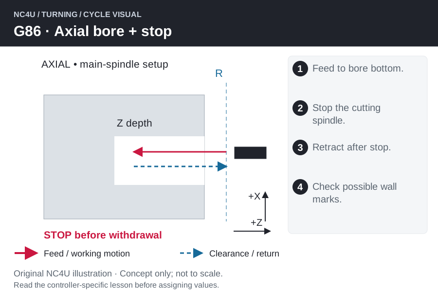
G86 feeds into the bore, stops the spindle at the bottom and retracts after it has stopped. The rapid return can shorten withdrawal time, but a stationary cutting edge may mark the bore. Choose it only when this exit behaviour fits the tool and surface requirement.
How the cycle works
- Identify an on-centre axial or supported live-tool setup, then position clear of the intended hole.
- Approach the R position with a verified tool/work offset.
- Feed to the Z endpoint, then let the control stop the spindle before return begins.
- Retract rapidly from the bore after the stop; verify the subsequent spindle state before the next cut.
Read the program words
| Word | Meaning |
|---|---|
R | Axial approach-plane position, chosen from the actual face and clearance. |
Z | Axial bottom coordinate; distinguish tool-tip depth from full feature depth. |
F | Feed: identify the active lathe feed mode and the rotating spindle. |
Read the cycle format
A syntax sketch with placeholders, not a complete runnable program.
G86 Z[bottom] R[approach] F[feed]Worked learning example
A bore can be correct in diameter yet have a visible axial scratch after withdrawal. That symptom suggests checking the exit method, edge position and tool clearance, rather than changing only the programmed Z depth.
Common mistakes and setup checks
- A spindle stop is not automatically an oriented spindle plus a lateral tool-clearance shift. Do not assume fine-boring behaviour.
- Cancel the hole cycle with G80 before unrelated positioning. Lathe G98/G99 select feed units; they are not milling return-plane commands.
G85 feeds out with rotation continuing; G86 stops then retracts. A radial live-tool bore uses the corresponding supported radial function rather than an unverified axial block.
LESSON 17 / TURNING
G89 · Axial boring with dwell and feed return
Haas lathe · controller-specific learning example
G89 combines feed entry, a bottom dwell and feed withdrawal for an axial bore. A controlled pause can be useful at a bore shoulder, but its duration needs a process reason. The cycle does not compensate for a blunt tool, excessive overhang or an unstable workholding setup.

How the cycle works
- Identify an on-centre axial or supported live-tool setup, then position clear of the intended hole.
- Approach the R position with a verified tool/work offset.
- Feed to the bottom position, maintain rotation and dwell for P.
- Withdraw at feed, then return to the clear positioning region before moving to another feature.
Read the program words
| Word | Meaning |
|---|---|
R | Axial approach-plane position, chosen from the actual face and clearance. |
Z | Axial bottom coordinate; distinguish tool-tip depth from full feature depth. |
F | Feed: identify the active lathe feed mode and the rotating spindle. |
P | Bottom dwell; confirm time units for this control. |
Read the cycle format
A syntax sketch with placeholders, not a complete runnable program.
G89 Z[bottom] R[approach] P[dwell] F[feed]Worked learning example
If a selected dwell is 0.5 seconds per hole, twelve holes add 6 seconds of dwell alone. Compare finish before and after a controlled trial; adding dwell without a measurable benefit simply adds cycle time and may increase rubbing.
Common mistakes and setup checks
- Confirm P time units and the bottom clearance for the boring bar; a pause must not become a collision with a blind shoulder.
- Cancel the hole cycle with G80 before unrelated positioning. Lathe G98/G99 select feed units; they are not milling return-plane commands.
G85 omits the dwell. G82 has a dwell but returns rapidly, so it should not be treated as the same boring sequence.
LESSON 18 / TURNING
G84 · Axial right-hand tapping
Haas lathe · controller-specific learning example
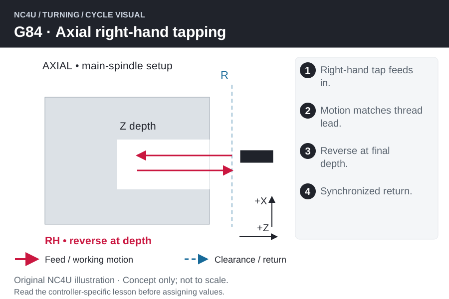
G84 produces an axial right-hand thread by matching axial movement to spindle rotation. This lesson concerns the main-spindle tapping arrangement on a Haas lathe. The tap must match the thread hand and predrilled hole; selecting the cycle does not determine the tap-drill size or required usable thread depth.
How the cycle works
- Prepare a correctly sized drilled hole, chamfer and suitable tap/holder.
- Call the tapping RPM before the cycle and establish the required feed-per-revolution relationship.
- Approach R and tap to the Z endpoint with the spindle direction required for the right-hand thread.
- Reverse the coordinated motion to withdraw along the same thread helix; clear the hole and cancel before unrelated movement.
Read the program words
| Word | Meaning |
|---|---|
S | Tapping RPM must be issued before this Haas cycle. |
F | With G99, F equals thread lead per revolution. |
Z / R | Tap endpoint and clear approach position. |
Read the cycle format
A syntax sketch with placeholders, not a complete runnable program.
G84 Z[tap-end] R[approach] F[lead-in-G99]Worked learning example
An M8 × 1.25 single-start right-hand thread needs 1.25 mm axial travel per revolution. At 400 rpm, the equivalent linear rate is 500 mm/min. These figures explain synchronisation only; a blind-hole tap also needs space for its chamfer and chips beyond the usable thread.
Common mistakes and setup checks
- Do not substitute a feed chosen for drilling; the tap lead fixes the movement ratio.
- Main-spindle tapping, axial live-tool tapping and radial live-tool tapping use different Haas functions.
G184 is the left-hand counterpart. G95 is the axial live-tool cycle; choose it only for the correct driven-tool configuration.
LESSON 19 / TURNING
G184 · Axial left-hand tapping
Haas lathe · controller-specific learning example
G184 produces an axial left-hand thread by matching axial movement to spindle rotation. This lesson concerns the main-spindle tapping arrangement on a Haas lathe. The tap must match the thread hand and predrilled hole; selecting the cycle does not determine the tap-drill size or required usable thread depth.

How the cycle works
- Prepare a correctly sized drilled hole, chamfer and suitable tap/holder.
- Call the tapping RPM before the cycle and establish the required feed-per-revolution relationship.
- Approach R and tap to the Z endpoint with the spindle direction required for the left-hand thread.
- Reverse the coordinated motion to withdraw along the same thread helix; clear the hole and cancel before unrelated movement.
Read the program words
| Word | Meaning |
|---|---|
S | Tapping RPM must be issued before this Haas cycle. |
F | With G99, F equals thread lead per revolution. |
Z / R | Tap endpoint and clear approach position. |
Read the cycle format
A syntax sketch with placeholders, not a complete runnable program.
G184 Z[tap-end] R[approach] F[lead-in-G99]Worked learning example
An M8 × 1.25 single-start left-hand thread needs 1.25 mm axial travel per revolution. At 400 rpm, the equivalent linear rate is 500 mm/min. These figures explain synchronisation only; a blind-hole tap also needs space for its chamfer and chips beyond the usable thread.
Common mistakes and setup checks
- Do not substitute a feed chosen for drilling; the tap lead fixes the movement ratio.
- Main-spindle tapping, axial live-tool tapping and radial live-tool tapping use different Haas functions.
G84 is the right-hand counterpart. G186 is the left-hand axial live-tool cycle, not the same spindle arrangement.
LESSON 20 / TURNING
G95 · Live-tool face tapping: right-hand
Haas lathe · controller-specific learning example
G95 uses a driven axial tap to thread a face hole on a suitably equipped Haas turning centre. The work is positioned for the hole while the live tool provides tapping rotation. This differs from tapping an on-centre hole by rotating the main spindle and keeping the tap stationary.

How the cycle works
- Position the face hole with the supported X/Y/C axes and establish clear axial approach.
- Select the required tapping RPM before the cycle and the supported G99 feed-per-revolution mode.
- Advance the live tap along Z with rotation coordinated for the right-hand thread.
- Reverse synchronously, withdraw clear, then index to the next intended hole only after checking clearance.
Read the program words
| Word | Meaning |
|---|---|
C / X / Y | Hole position: C is angular; X follows the machine diameter convention. |
Z / R | Axial tapping endpoint and approach plane. |
S / F | Prior RPM and feed equal to lead in G99. |
Read the cycle format
A syntax sketch with placeholders, not a complete runnable program.
G95 C[hole-angle] Z[tap-end] R[approach] F[lead]Worked learning example
Four equally spaced face holes can be indexed at 0°, 90°, 180° and 270°. A 40 mm pitch-circle diameter puts their centres 20 mm from the spindle axis. Check X diameter programming and any Y offset instead of treating a 20 mm radial distance as X20 automatically.
Common mistakes and setup checks
- For Haas G95, the documented X-position restriction is between machine zero and main-spindle centre; do not position beyond spindle centre.
- Confirm live-tool capability, handedness and full usable thread depth, including tap chamfer clearance.
G186 supplies the opposite thread hand. Radial live-tool holes use G195/G196; G95 here does not mean milling feed per revolution.
LESSON 21 / TURNING
G186 · Live-tool face tapping: left-hand
Haas lathe · controller-specific learning example
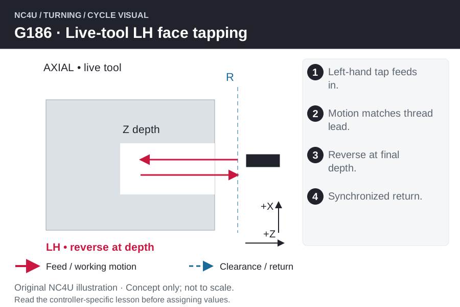
G186 uses a driven axial tap to thread a face hole on a suitably equipped Haas turning centre. The work is positioned for the hole while the live tool provides tapping rotation. This differs from tapping an on-centre hole by rotating the main spindle and keeping the tap stationary.
How the cycle works
- Position the face hole with the supported X/Y/C axes and establish clear axial approach.
- Select the required tapping RPM before the cycle and the supported G99 feed-per-revolution mode.
- Advance the live tap along Z with rotation coordinated for the left-hand thread.
- Reverse synchronously, withdraw clear, then index to the next intended hole only after checking clearance.
Read the program words
| Word | Meaning |
|---|---|
C / X / Y | Hole position: C is angular; X follows the machine diameter convention. |
Z / R | Axial tapping endpoint and approach plane. |
S / F | Prior RPM and feed equal to lead in G99. |
Read the cycle format
A syntax sketch with placeholders, not a complete runnable program.
G186 C[hole-angle] Z[tap-end] R[approach] F[lead]Worked learning example
Four equally spaced face holes can be indexed at 0°, 90°, 180° and 270°. A 40 mm pitch-circle diameter puts their centres 20 mm from the spindle axis. Check X diameter programming and any Y offset instead of treating a 20 mm radial distance as X20 automatically.
Common mistakes and setup checks
- For Haas G95, the documented X-position restriction is between machine zero and main-spindle centre; do not position beyond spindle centre.
- Confirm live-tool capability, handedness and full usable thread depth, including tap chamfer clearance.
G95 supplies the opposite thread hand. Radial live-tool holes use G195/G196; G95 here does not mean milling feed per revolution.
LESSON 22 / TURNING
G241 · Radial drilling with a live tool
Haas lathe · controller-specific learning example
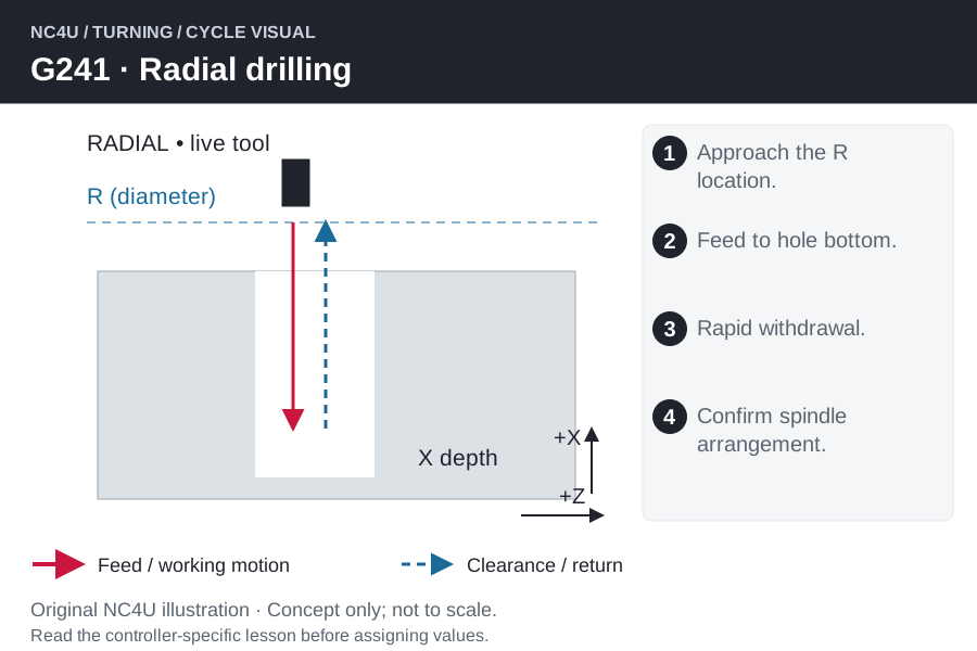
G241 drills from the outside of a turned component toward its centre using a radial live tool. The cutting stroke is along X, while Z locates the hole along the component and C selects its angular position. This is a different setup from an axial hole in the end face.
How the cycle works
- Fit a compatible radial live tool and establish the work/tool offsets.
- Position and restrain the work at the required C angle; select clear R and supported live-spindle operation.
- Feed inward along X from the R approach diameter to the programmed bottom diameter.
- Retract clear after the continuous drilling stroke; there is no deliberate peck or bottom dwell.
Read the program words
| Word | Meaning |
|---|---|
X / R | Bottom and approach positions in the radial cycle; confirm diameter programming. |
C / Z / Y | Angular and longitudinal hole location; Y offset only where supported. |
F | Feed rate; Haas radial drilling/boring examples use G98 feed per minute. |
Read the cycle format
A syntax sketch with placeholders, not a complete runnable program.
G241 X[bottom-diameter] R[approach-diameter] C[angle] Z[axial-location] F[feed]Worked learning example
For a 50 mm OD part with a radial hole tip 8 mm below the surface, the ideal diameter-coordinate endpoint is X34: 50 − 2 × 8. An R diameter of 54 gives 2 mm physical radial clearance, not 4 mm.
Common mistakes and setup checks
- A curved entry surface can deflect a drill. Plan the entry preparation and drill geometry rather than relying on the canned cycle alone.
- Cancel with G80 before unrelated positioning; check the complete tool-holder envelope around jaws and neighbouring features.
G242 adds bottom dwell and G243 adds chip-clearing pecks. Axial G81 uses Z as the hole-depth direction instead.
LESSON 23 / TURNING
G242 · Radial spot drilling with dwell
Haas lathe · controller-specific learning example
G242 adds a bottom dwell to a radial drilling stroke. It can serve a spot or suitable counterbore operation on the circumference of a component using live tooling. The depth direction is X, so its geometric interpretation must not be copied directly from a mill Z-depth example.
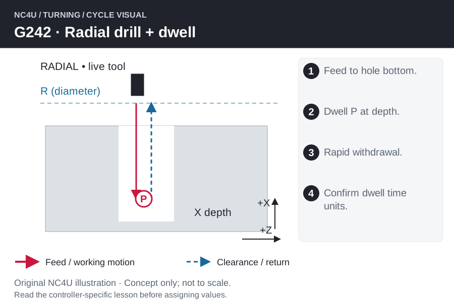
How the cycle works
- Fit a compatible radial live tool and establish the work/tool offsets.
- Position and restrain the work at the required C angle; select clear R and supported live-spindle operation.
- Feed along X to the requested bottom diameter and dwell there for P.
- After the dwell, withdraw rapidly and regain radial clearance before angular or axial repositioning.
Read the program words
| Word | Meaning |
|---|---|
X / R | Bottom and approach positions in the radial cycle; confirm diameter programming. |
C / Z / Y | Angular and longitudinal hole location; Y offset only where supported. |
F | Feed rate; Haas radial drilling/boring examples use G98 feed per minute. |
P | Dwell at the bottom; confirm the time-input convention. |
Read the cycle format
A syntax sketch with placeholders, not a complete runnable program.
G242 X[bottom-diameter] R[approach-diameter] C[angle] Z[axial-location] P[dwell] F[feed]Worked learning example
On a 60 mm OD, moving from surface X60 to X58 corresponds to 1 mm of radial tool penetration. Spot diameter also depends on the spot-tool angle and the curved entry surface; the 2 mm change in X is not automatically a 2 mm hole depth.
Common mistakes and setup checks
- P is a dwell value, not a peck depth or a subprogram number in this block. Confirm its time units.
- Cancel with G80 before unrelated positioning; check the complete tool-holder envelope around jaws and neighbouring features.
G241 omits dwell. G242 remains modal until cancelled or replaced, so an unintended following Y/Z positioning block may repeat the operation.
LESSON 24 / TURNING
G243 · Radial peck drilling with chip clearing
Haas lathe · controller-specific learning example
G243 drills a radial hole in separate pecks so chips can be withdrawn from the hole. A radial live tool supplies rotation while the component remains correctly indexed. The complete path includes entry, deeper cuts and clearance returns, not just the final X depth.
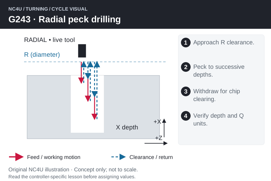
How the cycle works
- Fit a compatible radial live tool and establish the work/tool offsets.
- Position and restrain the work at the required C angle; select clear R and supported live-spindle operation.
- Feed the next increment along X, withdraw for chip clearing and re-approach before continuing deeper.
- Repeat until the bottom X is reached, then return clear for the next hole position.
Read the program words
| Word | Meaning |
|---|---|
X / R | Bottom and approach positions in the radial cycle; confirm diameter programming. |
C / Z / Y | Angular and longitudinal hole location; Y offset only where supported. |
F | Feed rate; Haas radial drilling/boring examples use G98 feed per minute. |
Q | Constant cut-in increment; verify its units independently of endpoint X. |
I / J / K | Alternative: initial peck, decrease per peck and minimum peck. |
Read the cycle format
A syntax sketch with placeholders, not a complete runnable program.
G243 X[bottom-diameter] R[approach-diameter] C[angle] Z[axial-location] Q[peck] F[feed]Worked learning example
A 10 mm physical radial depth in a diameter-programmed setup changes X by 20 mm. Before planning pecks, separate this endpoint conversion from the peck-argument convention. Verify Q or I/J/K in the exact control manual; do not automatically halve or double every address because X is diametral.
Common mistakes and setup checks
- Choose either constant Q or the I/J/K variable-peck scheme. Chips must actually clear the bore; a programmed retract alone is not evidence of evacuation.
- Cancel with G80 before unrelated positioning; check the complete tool-holder envelope around jaws and neighbouring features.
G241 has one continuous drilling feed; G243 repeats cutting and clearance. It is the radial counterpart to the axial G83 concept, with different depth coordinates.
LESSON 25 / TURNING
G245 · Radial boring with feed withdrawal
Haas lathe · controller-specific learning example
G245 bores an existing radial hole using a driven boring tool. The axial location of the hole is set by Z, its angular location by C, and its depth by X. Controlled feed withdrawal distinguishes the operation from a simple rapid-out drilling stroke.
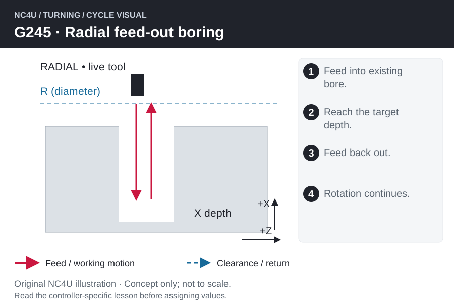
How the cycle works
- Fit a compatible radial live tool and establish the work/tool offsets.
- Position and restrain the work at the required C angle; select clear R and supported live-spindle operation.
- Feed the boring tool inward from radial clearance toward the bottom X position.
- Withdraw at feed while rotation continues, then regain clearance for any repositioning.
Read the program words
| Word | Meaning |
|---|---|
X / R | Bottom and approach positions in the radial cycle; confirm diameter programming. |
C / Z / Y | Angular and longitudinal hole location; Y offset only where supported. |
F | Feed rate; Haas radial drilling/boring examples use G98 feed per minute. |
Read the cycle format
A syntax sketch with placeholders, not a complete runnable program.
G245 X[bottom-diameter] R[approach-diameter] C[angle] Z[axial-location] F[feed]Worked learning example
For a bore at Z−25 mm on a 50 mm OD, Z locates the hole along the shaft; it does not give the radial depth. A bottom at X30 lies 10 mm physically below the outside surface in the illustrated diameter mode.
Common mistakes and setup checks
- Check minimum pilot-hole size, boring-head clearance and reach. The driven holder envelope can collide before the cutting tip reaches the intended bottom.
- Cancel with G80 before unrelated positioning; check the complete tool-holder envelope around jaws and neighbouring features.
G246 stops rotation before withdrawal. G249 adds dwell. Select the exit sequence for the tool and surface requirement, not just because the code name contains “boring”.
LESSON 26 / TURNING
G246 · Radial boring with spindle stop
Haas lathe · controller-specific learning example
G246 feeds into a radial bore and stops the live spindle at the bottom before retracting. It is a supported radial boring function on Haas machines with the required hardware. The stopped exit may leave a witness line, so the method must fit the surface-finish requirement.

How the cycle works
- Fit a compatible radial live tool and establish the work/tool offsets.
- Position and restrain the work at the required C angle; select clear R and supported live-spindle operation.
- Feed along X to the programmed bottom and stop the rotating tool.
- Retract only after the spindle has stopped, then recover a clear position before another hole is indexed.
Read the program words
| Word | Meaning |
|---|---|
X / R | Bottom and approach positions in the radial cycle; confirm diameter programming. |
C / Z / Y | Angular and longitudinal hole location; Y offset only where supported. |
F | Feed rate; Haas radial drilling/boring examples use G98 feed per minute. |
Read the cycle format
A syntax sketch with placeholders, not a complete runnable program.
G246 X[bottom-diameter] R[approach-diameter] C[angle] Z[axial-location] F[feed]Worked learning example
If a finished radial bore shows a line in the withdrawal direction, check the stopped cutting-edge contact and clearance. Altering C position does not fix an exit scratch; C defines where the hole is, while the return sequence determines how the edge leaves it.
Common mistakes and setup checks
- Do not assume this function supplies spindle orientation or a lateral edge-clearance move. Confirm the actual machine sequence and tool geometry.
- Cancel with G80 before unrelated positioning; check the complete tool-holder envelope around jaws and neighbouring features.
G245 feeds out while rotating; G246 stops before withdrawal. G86 is the axial stop-and-retract counterpart and uses a different hole-depth direction.
LESSON 27 / TURNING
G249 · Radial boring with dwell
Haas lathe · controller-specific learning example
G249 adds a bottom dwell to a radial boring sequence before feed withdrawal. It can help a planned finishing operation at a radial bore shoulder, but the dwell must be justified by the tool and material. It does not correct an oversized pilot hole or an unstable boring tool.
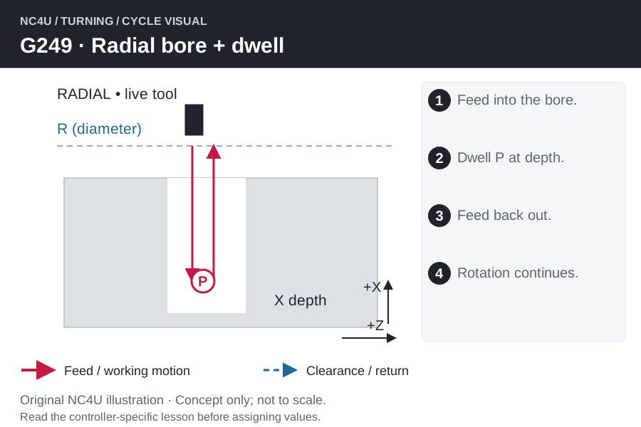
How the cycle works
- Fit a compatible radial live tool and establish the work/tool offsets.
- Position and restrain the work at the required C angle; select clear R and supported live-spindle operation.
- Feed the driven boring tool to X bottom and dwell for the selected P time.
- Withdraw at feed after dwell, keeping the return path clear before indexing another position.
Read the program words
| Word | Meaning |
|---|---|
X / R | Bottom and approach positions in the radial cycle; confirm diameter programming. |
C / Z / Y | Angular and longitudinal hole location; Y offset only where supported. |
F | Feed rate; Haas radial drilling/boring examples use G98 feed per minute. |
P | Dwell at the bottom; confirm the time-input convention. |
Read the cycle format
A syntax sketch with placeholders, not a complete runnable program.
G249 X[bottom-diameter] R[approach-diameter] C[angle] Z[axial-location] P[dwell] F[feed]Worked learning example
A 0.25-second dwell repeated at eight radial holes contributes 2 seconds of stationary feed time. Compare the shoulder finish during a controlled trial. If the pause leaves a ring or burns the surface, increasing dwell is unlikely to solve the underlying tool or process issue.
Common mistakes and setup checks
- P is modal on this control; a reused P for another function can affect the intended dwell. Read the complete surrounding program.
- Cancel with G80 before unrelated positioning; check the complete tool-holder envelope around jaws and neighbouring features.
G245 has no deliberate bottom dwell. G242 also dwells, but is a spot-drilling sequence with rapid withdrawal rather than this boring feed-out strategy.
LESSON 28 / TURNING
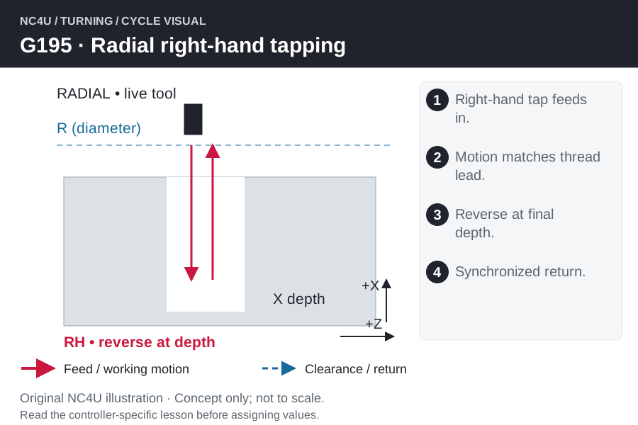
G195 · Radial live-tool tapping: forward / right-hand
Haas lathe · controller-specific learning example
G195 taps from the circumference using a radial driven tool, with synchronised X travel and tool rotation. This forward / right-hand function requires the compatible live-tool setup. The part is angularly positioned for the hole rather than continuously rotating as it would during ordinary turning.
How the cycle works
- Prepare the radial pilot hole and confirm tap hand, holder reach and entry chamfer.
- Index the part, establish clearance and call a positive tapping RPM before the cycle.
- Tap inward toward the X endpoint with G99 feed equal to the required thread lead.
- Reverse synchronously and withdraw along the thread; cancel the modal cycle before unrelated repositioning.
Read the program words
| Word | Meaning |
|---|---|
X / R | Radial bottom and approach positions; diameter interpretation must match the setup. |
C / Z | Hole angle and longitudinal position. |
S | Positive tapping RPM issued before the cycle. |
F | In G99, the thread lead per revolution, not a diameter-coordinate difference. |
Read the cycle format
A syntax sketch with placeholders, not a complete runnable program.
G195 X[tap-end-diameter] R[approach] F[lead-in-G99]Worked learning example
For a 1 mm-lead tap, one tool revolution requires 1 mm physical axial motion along the tap, even when X endpoints are programmed as diameters. On a 40 mm OD, a radial endpoint 6 mm below the surface is X28 in diameter mode. Do not double the tapping lead to match that endpoint convention.
Common mistakes and setup checks
- Blind radial holes need clearance for the tap chamfer and chips before reaching an internal bore or opposite wall.
- Confirm the supported synchronised tapping mode; drilling feed overrides are not a substitute for a correct lead.
G196 is the opposite-hand radial function. G95/G186 tap face holes along Z; G84/G184 use the main-spindle axial arrangement.
LESSON 29 / TURNING
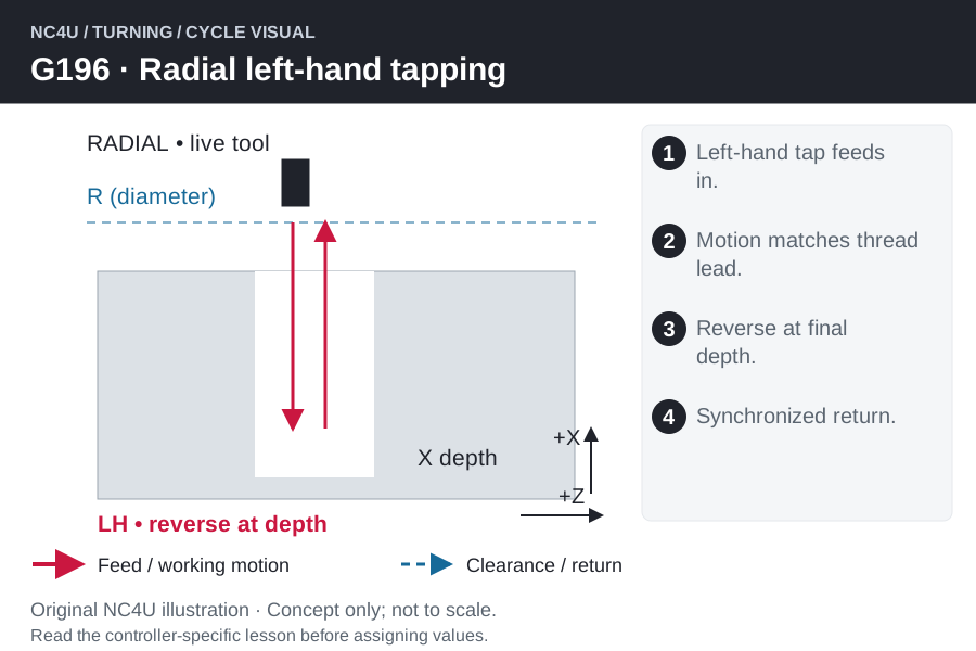
G196 · Radial live-tool tapping: reverse / left-hand
Haas lathe · controller-specific learning example
G196 taps from the circumference using a radial driven tool, with synchronised X travel and tool rotation. This reverse / left-hand function requires the compatible live-tool setup. The part is angularly positioned for the hole rather than continuously rotating as it would during ordinary turning.
How the cycle works
- Prepare the radial pilot hole and confirm tap hand, holder reach and entry chamfer.
- Index the part, establish clearance and call a positive tapping RPM before the cycle.
- Tap inward toward the X endpoint with G99 feed equal to the required thread lead.
- Reverse synchronously and withdraw along the thread; cancel the modal cycle before unrelated repositioning.
Read the program words
| Word | Meaning |
|---|---|
X / R | Radial bottom and approach positions; diameter interpretation must match the setup. |
C / Z | Hole angle and longitudinal position. |
S | Positive tapping RPM issued before the cycle. |
F | In G99, the thread lead per revolution, not a diameter-coordinate difference. |
Read the cycle format
A syntax sketch with placeholders, not a complete runnable program.
G196 X[tap-end-diameter] R[approach] F[lead-in-G99]Worked learning example
For a 1 mm-lead tap, one tool revolution requires 1 mm physical axial motion along the tap, even when X endpoints are programmed as diameters. On a 40 mm OD, a radial endpoint 6 mm below the surface is X28 in diameter mode. Do not double the tapping lead to match that endpoint convention.
Common mistakes and setup checks
- Blind radial holes need clearance for the tap chamfer and chips before reaching an internal bore or opposite wall.
- Confirm the supported synchronised tapping mode; drilling feed overrides are not a substitute for a correct lead.
G195 is the opposite-hand radial function. G95/G186 tap face holes along Z; G84/G184 use the main-spindle axial arrangement.
Learn it with an NC4U example
Start with a feature on a component: a hole, a pocket, a groove or a thread. Identify what the tool must do, choose a suitable cycle, then check the tool, offsets and clearance. Our diagrams explain the idea; the exact machine manual determines the supported syntax.
NC4U Solutions · Original learning notes and illustrations · Illustrated cycle edition.
Turn this knowledge into a practical skill.
Learn CNC setting, manual programming and Mastercam with NC4U in Coimbatore or Chennai, or join online from anywhere in India and worldwide. Discuss your current experience and preferred training language.